
AUDI 80 Schematic wiring diagram
A1 - control unit for the enrichment of the mixture;
A2 - commutator of the ignition system TSZ-H;
A3 - voltage regulator;
В - the accumulator battery;
F1 - F17 - fuses (factory numbering);
G - generator;
H1 - sound signal;
Н2 - the signaling device of falling of level of a brake liquid;
H3 - signaling device for engine overheating and coolant level drop; Н4 - the indicator of the right index of turn;
Н5 - the indicator of the left index of turn;
H6 - digital clock;
Н7 - a lamp of illumination of hours;
Н8 - warning lamp of the alarm system;
Н9 - the indicator of inclusion of dimensional illumination;
Н10 - the index of temperature of a cooling liquid;
Н11 - the index of level of fuel in a tank;
Н12 - signaling device for emergency oil pressure;
H13 - indicator of the applied parking brake;
Н14 - the indicator of inclusion of a starter;
H15 - generator fault indicator;
Н16 - a speedometer;
K1 - bus relay "X";
K2 - electronic relay-buzzer;
К3 - the relay of inclusion of heating of an inlet collector;
К4 - the control device of the indicator of emergency pressure of oil;
K5 - cooling fan relay;
K6 - the relay of a sound signal;
К7 - the electronic relay of the index of turn;
K8 - the electronic relay of management of a screen wiper;
К9 - the relay of a windshield wiper;
L - ignition coil;
M1 - starter;
M2 - cooling fan;
M3 - windshield wiper;
M4 - windscreen washer pump;
M5 - the pump of a windshield washer;
M6 - fan of the heating system;
Р1 - the gauge of the Hall of the distributor of ignition;
Р2 - the gauge of temperature of a cooling liquid;
Р3 - the gauge of a speedometer;
Р4 - the gauge of level of fuel;
R1 - carburettor heater;
R2 - the heater of an inlet collector;
R3 - brightness control of the illumination of the instrument cluster;
R4 - cigarette lighter;
R5 - the heater of back glass;
S1 - the ignition switch;
S2 - thermal contact device;
S3 - thermal switch for heating the intake manifold;
S4 - the ignition distributor;
S5 - the gauge of pressure of oil on 1,8 bar;
S6 - oil pressure sensor at 0.3 bar;
S7 - thermal coolant fan switch;
S8 - stop light switch;
S9 - light switch;
S10 - contact group for flashing lights;
S11 - the switch of illumination of a luggage carrier;
S12 - reversing light switch;
S13 - the button of a sound signal;
S14 - the switch of indexes of turn;
S15 - alarm switch;
S16-S19 - door switches left front, left rear, right front and right rear doors respectively;
S20 - the switch of a screen wiper;
S21 - the gauge of level of a cooling liquid;
S22 - the level gauge of a brake liquid;
S23 - electronic clock setting button;
S24 - the gauge of inclusion of a lay brake;
S25 - sensor of the starter;
S26 - heating fan switch;
S27 - the switch of a heater of back glass;
W1 - left rear direction indicator;
W2 - left rear position lamp;
W3-W4 - brake lights;
W5 - right rear position lamp;
W6 - right rear direction indicator;
W7, W8 - the left headlight;
W9, W10 - right headlight;
W11, W12 - left and right front parking lights;
W13 - glove box lighting lamp;
W14 - lamps of illumination of a panel;
W15 - a lamp of illumination of a luggage carrier;
W16 - the lamp for lighting the engine compartment;
W17, W18 - reversing lights;
W19, W20 - right and left front direction indicators;
W21 - interior lighting;
W22-W27 - lamps of illumination of a combination of devices;
W28 - the light of the cigarette lighter;
X1-X19 - connectors (the color in the diagram corresponds to the color of the connector housing), installed: X1 - right on the apron;
X2 - near the ignition distributor;
X3 - near the carburetor;
X4 - near the valve Y2;
X5 - near the intake manifold;
X6, X7, X9, X11, X12 - near the assembly block;
X8 - in the trunk on the left;
Х10, Х13, Х17 - on the left behind the panel of devices;
X14 - on the left behind the instrument cluster;
Х16 - on the instrument cluster (yellow);
X18 - on the instrument cluster (blue);
X19 - in the middle of the instrument panel;
Y1 - the valve for enriching the mixture;
Y2 - excess air valve;
Y3 - carburetor nozzle valve
ELECTRICAL EQUIPMENT DIAGRAM FOR AUDI-80 1,8S
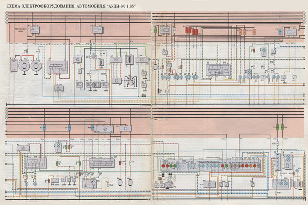
Points of connection of consumers with the "mass" (indicated in the circles in the circles near the bus bar):
1 - in the wiring harness of the instrument panel;
2 - in the battery compartment;
3 - in the front right harness;
4 - in the front left wiring harness;
5 - in a plait of wires behind the engine compartment;
6 - left in the trunk;
7 - on the left behind the instrument panel.
Diagram of the location of the connectors and their contacts in the mounting block (on the electrical equipment diagram, the connection of the wire, for example to terminal 75al of connector J, is indicated by J / 75al).
kk_wiring (Monday, 06 March 2023 20:54)
need manual
Florin Serban (Thursday, 08 October 2020 11:16)
Audi 80