
Audi A3 Electrical Wiring Diagrams
|
Audi A3 2004 – Self Study Programme 312 - Electrical Wiring Diagrams.pdf |
2.7Mb |
|
2 |
band mass, PPC-car body |
|
10 |
point mass in catchment compartment |
|
11 |
point mass in a box battery |
|
12 |
point mass, in the engine compartment on the left |
|
42 |
point mass around the steering column |
|
43 |
point mass, and bottom right |
|
45 |
point mass behind the dash, in the Center |
|
49 |
point mass around the steering column left |
|
50 |
point masses, the trunk on the left |
|
85 |
join mass-1-in the motor compartment wiring harness |
|
98 |
join the masses in the tailgate wiring harness |
|
128 |
join mass-1-in the wiring harness internal lighting |
|
162 |
join the masses in the wiring harness fan motor |
|
200 |
connecting mass (shielding), wiring harness motor compartment |
|
205 |
mass connection, wiring harness door driver side |
|
206 |
join the masses in the wiring harness door-passenger side |
|
220 |
mass connection, wiring harness engine |
|
238 |
join mass-1-in the wiring harness of the Salon |
|
249 |
join mass-2-in the wiring harness of the Salon |
|
255 |
join mass-1-in the wiring harness to the radio |
|
277 |
join mass-3-, the wiring harness of the Salon |
|
278 |
join mass-4-in the wiring harness of the Salon |
|
279 |
join mass-5-in the wiring harness of the Salon |
|
280 |
connection-2-in wiring harness motor compartment |
|
281 |
join mass-1-in the engine wiring harness |
|
283 |
join mass-2-in the engine wiring harness |
|
285 |
join mass-7 is in the wiring harness of the Salon |
|
(A) |
rechargeable battery |
|
A1 |
positive connection (30A) in the instrument panel wiring harness |
|
A2 |
positive connection-15-in the wiring harness in the dash |
|
A3 |
positive connection-58-wiring harness in the dash |
|
A15 |
positive connection-15-wiring harness in the dash |
|
A15 |
connection (30al) instrument panel wiring harness |
|
A18 |
connection-54-in the wiring harness in the dash |
|
A21 |
positive connection (86s), instrument panel wiring harness |
|
A23 |
positive connection-15-wiring harness in the dash |
|
A24 |
connection (braking system control), wiring harness instrument panel |
|
A27 |
connection (speed signal) instrument panel wiring harness |
|
A45 |
connection (speed signal) instrument panel wiring harness |
|
A46 |
positive connection (30-from the radio) in the instrument panel wiring harness |
|
A50 |
positive connection (30as) instrument panel wiring harness |
|
A51 |
connection-56-in instrument panel wiring harness |
|
A72 |
connection-71-instrument panel wiring harness |
|
A76 |
connection (wire diagnostic) instrument panel wiring harness |
|
A80 |
connection-1-(x) in the instrument panel wiring harness |
|
A81 |
connection-2-(x) in the instrument panel wiring harness |
|
A84 |
connection (58 L), instrument panel wiring harness |
|
A85 |
connection (58R) instrument panel wiring harness |
|
A86 |
connection (50A) in dashboard wiring harness |
|
A87 |
connection (RF), instrument panel wiring harness |
|
A88 |
connection (NSL) wiring harness instrument panel |
|
A89 |
connection-54-in instrument panel wiring harness |
|
A97 |
connection-53-wiring harness in the dash |
|
A98 |
positive connection-4-(30A) in the instrument panel wiring harness |
|
A99 |
connection-1--87-wiring harness in the dash |
|
A100 |
connection-2---87) in the instrument panel wiring harness |
|
A101 |
connection-3--87-wiring harness in the dash |
|
A103 |
connection-2--56-in instrument panel wiring harness |
|
A107 |
connection (convenience close) in the instrument panel wiring harness |
|
A108 |
connection (speed signal) instrument panel wiring harness |
|
A114 |
connection (adjustment range of light), the instrument panel wiring harness |
|
A121 |
connection (High-Bus) in the instrument panel wiring harness |
|
A122 |
connection (Low-Bus) in the instrument panel wiring harness |
|
A125 |
connection (Crash-signal) in the instrument panel wiring harness |
|
(B) |
Starter |
|
B114 |
connection (safety switch) wiring harness Salon |
|
B115 |
positive connection (30A) in the wiring harness of the Salon |
|
B116 |
connection (58 d) wiring harness Salon |
|
B117 |
connection (58 and right), the wiring harness of the Salon |
|
B126 |
connection (87, device management window), window regulator wiring harness |
|
B131 |
a positive connection is 54-is in the wiring harness of the Salon |
|
B135 |
connection (15A), the wiring harness of the Salon |
|
B138 |
a positive connection is 1-(x) in the wiring harness of the Salon |
|
B139 |
connection (PL), the wiring harness of the Salon |
|
B140 |
connection (PR), the wiring harness of the Salon |
|
B142 |
positive connection-2-(and 56), the wiring harness of the Salon |
|
B143 |
positive connection (58R) wiring harness Salon |
|
B144 |
positive connection (58L) in the wiring harness of the Salon |
|
B145 |
positive connection (58b) in the wiring harness of the Salon |
|
B147 |
positive connection-2--87-the wiring harness of the Salon |
|
B149 |
positive connection-2-(15A), the wiring harness of the Salon |
|
B150 |
positive connection-2-a (30 a) wiring harness Salon |
|
B152 |
link (BL), the wiring harness of the Salon |
|
B153 |
connection (BR), the wiring harness of the Salon |
|
B154 |
connection-1-(TC), the wiring harness of the Salon |
|
B155 |
connection-2-(TC), the wiring harness of the Salon |
|
B156 |
positive connection-4-(30a) in the wiring harness of the Salon |
|
B156 |
connection-2-(TC), the wiring harness of the Salon |
|
B160 |
connection (brake system control), wiring harness elephant |
|
B165 |
connection-2-in the wiring harness of the Salon |
|
B175 |
connection (unified lock), the wiring harness of the Salon |
|
B178 |
connection (speed signal), the wiring harness of the Salon |
|
B211 |
connection-1-(rear of Unit) tow wiring compartment |
|
(C) |
generator |
|
C1 |
voltage regulator |
|
(D) |
ignition switch |
|
(D) |
switch cigarette lighter |
|
(D) |
positive connection (87) in the motor compartment wiring harness |
|
D2 |
Reader spool anti-theft protection |
|
D22 |
link (via fuse 234) in the wiring harness front right |
|
D78 |
a positive connection is 1-(30A) in the motor compartment wiring harness |
|
D80 |
positive connection (87 a) wiring harness motor compartment |
|
D140 |
connection (injector), engine wiring harness |
|
D141 |
connection (5V), engine wiring harness |
|
E1 |
light switch |
|
E2 |
switch turn signals |
|
E3 |
alarm switch |
|
E4 |
Manual dimming switch and signal light |
|
E9 |
fresh air blower switch |
|
E14 |
14-pin connector, cable channel, in the engine compartment on the left |
|
E15 |
heated rear window switch |
|
E18 |
fog lamp switch |
|
E19 |
parking light switch |
|
E20 |
dimmer switch switch and instrument panel |
|
E22 |
interval wiper switch mode |
|
E24 |
switch the driver's safety-belt |
|
E34 |
rear wiper switch |
|
E38 |
the interval knob enable the sanitiser |
|
E40 |
window lifter switch, front left (driver's door) |
|
E41 |
window lifter switch, front right (driver's door) |
|
E87 |
the control unit and the unit |
|
E102 |
range of light regulator |
|
E107 |
window lifter switch, right front (passenger doors) |
|
E150 |
internal lock switch, driver side |
|
E159 |
switch the flaps of fresh and recirculated air |
|
(F) |
brake light switch-signals |
|
F1 |
oil pressure switch |
|
F2 |
door contact switch, driver side |
|
F3 |
door contact switch, passenger side |
|
F4 |
reversing light switch |
|
F9 |
parking brake control switch |
|
F18 |
coolant fan switch |
|
F34 |
contact brake fluid level |
|
F36 |
clutch pedal switch |
|
F54 |
coolant fan switch |
|
F60 |
idling speed switch |
|
F66 |
switch coolant pointer |
|
F88 |
power steering switch |
|
F216 |
contact switch to disable fog lamp |
|
(G) |
fuel reserve sensor |
|
G1 |
pointer, fuel reserve |
|
G2 |
coolant temperature sensor |
|
G3 |
coolant temperature gauge |
|
G5 |
tachometer |
|
G6 |
fuel pump |
|
G12 |
reserve sensor/fuel level |
|
G14 |
voltmeter |
|
G17 |
ambient temperature sensor |
|
G21 |
speedometer |
|
G22 |
speedometer sensor (Hall sensor on PPC) |
|
G22 |
speedometer sensor (Hall sensor from PPC) |
|
G220 |
Motronic control unit |
|
G28 |
engine speed sensor |
|
G34 |
brake wear sensor, front left |
|
G39 |
oxygen sensor |
|
G40 |
Hall sensor |
|
G61 |
knock sensor 1 |
|
G62 |
coolant temperature sensor |
|
G66 |
knock sensor 2 |
|
G69 |
potentiometer throttle |
|
G70 |
air mass meter |
|
G88 |
potentiometer throttle actuator |
|
(H) |
enable audio signal |
|
H2 |
beep |
|
H3 |
buzzer/Gong |
|
H7 |
the sound woofer signal |
|
J4 |
dual-tone signal relays |
|
J2 |
alarm relay |
|
J17 |
fuel pump relay |
|
J30 |
Relay and washer rear window cleaner |
|
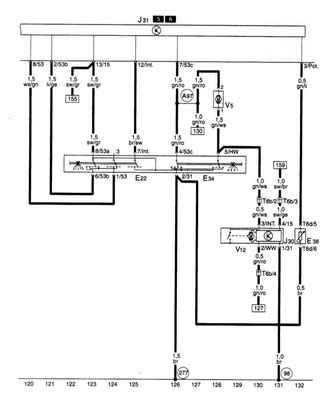
J31 |
interval relay automation Purifier-windscreen washer |
|
J59 |
handling the relay contact x |
|
J104 |
ABS control unit with EDS |
|
J124 |
Control appliance bulbs, rear |
|
J189 |
self-diagnostic system |
|
J217 |
device ATH |
|
J218 |
Combi-processor block dashboard |
|
J220 |
Motronic control unit |
|
J226 |
Relay Starter lockout and reversing light |
|
J234 |
airbag control unit |
|
J293 |
coolant fan control device |
|
J338 |
throttle control unit |
|
J361 |
device control to Simos |
|
J446 |
parking aid control unit |
|
K1 |
driving beam lamp |
|
K2 |
generator lamp |
|
K3 |
the oil pressure warning lamp |
|
K4 |
brake lamp light |
|
K14 |
parking brake lamp |
|
K149 |
motor electronics lamp |
|
K16 |
fuel reserve warning lamp |
|
K18 |
trailer lamp |
|
K19 |
safety belt warning lamp |
|
K28 |
coolant temperature warning lamp |
|
K32 |
brake lamp |
|
K37 |
washer fluid level warning lamp |
|
K47 |
the ABS lamp |
|
K65 |
lamp turn signal left |
|
K75 |
the airbag warning lamp |
|
K94 |
turn signal lamp right |
|
K102 |
closing lamp tailgate |
|
K117 |
lamp anti-theft protection |
|
K132 |
lamp failure the electric transmission of gas |
|
K134 |
adjust the level control lamp |
|
L1 |
dvuhnitevaja lamp headlamp left |
|
L2 |
dvuhnitevaja lamp lights right |
|
L9 |
backlight lamp light switch |
|
L15 |
Spotlight ashtray |
|
L28 |
backlight lamp lighter |
|
L40 |
Spotlight-switch Misty lamp |
|
L46 |
bulb fog lamp left |
|
L46 |
bulb fog lamp left |
|
L47 |
bulb fog lamp right |
|
L48 |
connection (15A), the wiring harness heater regulator (Thermotronic) |
|
L54 |
backlight lamp/light range regulator |
|
L66 |
connection in the wiring harness heater fan |
|
M1 |
lamp left side lights |
|
M2 |
side marker lamp lamp right |
|
M3 |
lamp right side lights |
|
M4 |
side marker lamp lamp left |
|
M5 |
front left turn signal lamp |
|
M6 |
lamp turn signal rear left |
|
M7 |
front right turn signal lamp |
|
M8 |
lamp turn signal rear right |
|
M9 |
stop lamp signal left |
|
M10 |
stop lamp signal right |
|
M16 |
reversing light lamp-left |
|
M17 |
reversing light lamp right |
|
M18 |
side Repeater lamp left |
|
M19 |
side Repeater lamp right |
|
M25 |
high lamp supplied stop-signal |
|
(N) |
ignition coil 1 |
|
N23 |
extension of fresh air fan resistor |
|
N30 |
cylinder 1 injector |
|
N31 |
cylinder 2 injector |
|
N32 |
Injector cylinder 3 |
|
N33 |
Injector cylinder 4 |
|
N79 |
resistor (crankcase ventilation) |
|
N80 |
solenoid valve 1 adsorber system |
|
N122 |
output output |
|
N128 |
ignition coil 2 |
|
No. 156 |
switching valve inlet piping |
|
N205 |
the regulator 1 camshaft |
|
N206 |
extension of warm air with fan resistor overheating fuse |
|
(P) |
Plug ignition coil |
|
Q |
spark plugs |
|
R34 |
connection-87-in wiring harness cables-driver side |
|
R35 |
connection-87-in wiring harness cables, door passenger side |
|
S37 |
fuse clips |
|
S131 |
fuse 1 |
|
S132 |
Fuse 2 |
|
S133 |
Fuse 3 |
|
S134 |
& fuse 4nbsp; |
|
S138 |
glass tube fuse 5 |
|
S162 |
1 in the fuse box/battery |
|
S163 |
2 in the box fuses/battery |
|
S164 |
3-in-a-box fuses/battery |
|
T1a |
1-pin connector, white, in the trunk on the left |
|
T2 |
Socket 2-pin in the right Bay catchment |
|
T2a |
Socket 2-pin, black, behind the instrument panel, right side |
|
T2c |
Socket 2-pin, black, tailgate right |
|
T2d |
Socket 2-pin, black, tailgate left |
|
T2f |
Socket 2-pin in the engine compartment on the left |
|
T2h |
Socket 2-pin in the right Bay catchment |
|
T2p |
Socket 2-pin behind the console |
|
T3b |
Connector 3-pin, blue, in the engine compartment |
|
T3b |
Connector 3-pin, black, in the engine compartment |
|
T3c |
Connector 3-pin, Brown, in the engine compartment |
|
T3d |
Connector 3-pin, white, in the engine compartment |
|
T3d |
3-pin connector, grey, in the engine compartment |
|
T3E |
Connector 3-pin, black, at the main fuse block/battery |
|
T3g |
Connector 3-pin, socket trailer |
|
T4 |
Connector 4-pin in the engine compartment on the right |
|
T4c |
Connector 4-pin behind the console |
|
T4j |
Connector 4-pin left headlamp |
|
T4l |
Connector 4-pin lights right |
|
T5 |
5-pin connector, right headlight |
|
T5a |
5-pin connector, yellow, behind the cladding podrulevogo switch |
|
T5b |
5-pin connector, the left headlight |
|
T6a |
6-pin connector, black, in the trunk on the left |
|
T6b |
6-pin connector, blue, in the trunk on the left |
|
T6d |
6-pin connector, Brown, behind the cladding podrulevogo switch |
|
T6m |
6-pin connector, Brown, Bay catchment |
|
T8 |
8-pin connector near the radio |
|
T8b |
6-pin connector, blue, in the trunk on the left |
|
T10 |
razem10-pin, white, catchment compartment |
|
T10b |
Connector 10-pin, gray, Bay catchment |
|
T10d |
Connector 10-pin, Brown, clutch-beam rack and left |
|
T10f |
Connector 10-pin, Brown, clutch-beam rack and left |
|
T10k |
10-pin connector, Orange, Bay catchment |
|
T10l |
10-pin connector, red, beam rack and adhesion, left |
|
T10m |
razem10-pin, red beam rack and adhesion, right |
|
T10n |
Connector 10-pin, the door to the left |
|
T10o |
razem10-pin in the door on the right |
|
T10x |
10-pin connector, Orange, Bay catchment |
|
T14 |
14-pin connector, cable channel, in the engine compartment on the left |
|
T16 |
16-pin connector, black, in the trunk on the left |
|
T16 |
16-pin connector Black regiment center console (diagnostic plug) |
|
T17 |
17-pin connector, black behind the instrument panel to the right |
|
T20 |
20-pin connector, black, block the dashboard |
|
T32 |
32-pin connector, blue, block the dashboard |
|
T32a |
Connector 32-pin, green the block dashboard |
|
T32b |
32-pin connector, grey block have dashboard |
|
U1 |
cigarette lighter |
|
U10 |
Socket trailer |
|
(V) |
Wiper motor |
|
V2 |
fan fresh air |
|
V5 |
windscreen washer pump |
|
V7 |
coolant fan |
|
V12 |
rear wiper motor |
|
V14 |
window lifter motor, left |
|
V15 |
window lifter motor, right |
|
V48 |
left motor control range of light |
|
V49 has been replaced |
the motor right control range of light |
|
V60 |
charge of the throttle |
|
V94 |
single motor control device for lock-off delay interior lighting lamps and anti-theft alarm |
|
V94 |
single motor control device for lock-off delay lights indoor lighting and anti-theft alarm |
|
V154 |
motor installation of fresh and recirculated air flap |
|
W6 |
lighting the glove box |
|
W9 |
coverage area of the legs to the left |
|
W10 |
coverage area of the legs on the right |
|
W18 |
trunk lamp left |
|
W35 |
trunk lamp right |
|
X |
lamp plate |
|
Y |
analog clock |
|
Z1 |
heated rear window |
|
Z19 |
oxygen sensor heater |
|
Z20 |
the heating resistor left nozzle |
|
Z21 |
the heating resistor right nozzle |
Designations on electric schemes

1 - Relay No. Indicates the location of the relay on the relay board.
2 - designation of the relay / control device on the relay board
The legend indicates the name of the element.
3 - designation of the fuse
For example, fuse No. 19 (10 A) on the fuse holder.
4 - the symbol for the plug connection on the relay board
For example, contact 3 / 49a:
3 pin 3 in place 12 of the relay board
49a terminal 49a on the relay / control unit.
5 - the symbol for the plug connection on the relay board
For example, A13 - multi-pin connector A, pin 13.
6 - wire cross-section, mm2
7 - wire color
8 - extruded number on a white wire
It facilitates identification with a large number of white wires of one bundle.
9 - designation of the connection terminal
With the terminal designation, which can be found on the original part.
10 - measuring point of the fault finding algorithm
The number in the black circle indicates a pattern or an algorithm for troubleshooting the AUDI.
11 - designation of the hazard switch
12 - element designation
The legend indicates the name of the element.
13 - indication of continuation of the wire
The number in the square indicates the coordinate of the continuation.
14 - internal communication (thin line)
This connection does not exist as a wire.
15 - indication of the continuation of the internal connection
The letter indicates where the connection continues in the nearest circuit element.
16 - mass point designation
The legend indicates the position of the mass point in the car.
17 - relay board with fuse holder
18 - cable
19 - coordinate of the chain
Mass connections (only for countries with a cold climate)

Mass Connections

Rechargeable battery, starter, generator, main fuse block / rechargeable battery

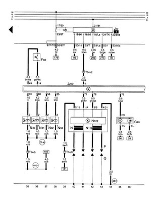
Control device for Motronic, fuel pump relay, injectors, ignition system, Hall sensor
Control device for Motronic, knock sensors, engine speed sensor, coolant temperature sensor

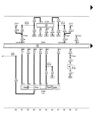
Control device for Motronic, throttle control unit
Control device for Motronic, oxygen sensor, air mass meter, camshaft control, adsorber purge solenoid valve, intake manifold switch

Cigarette lighter switch, unloading relay for contact X
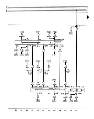
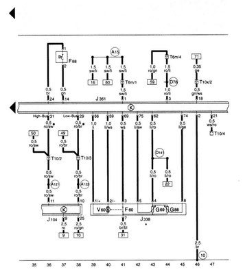
Light switch, steering column switch left
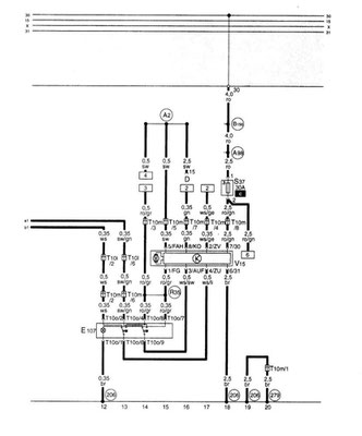
Dimmer switches and control devices, LDR, wiper and washer, LDR (not applicable to a system Motronic turbo 1.8 l 154 kW S3)
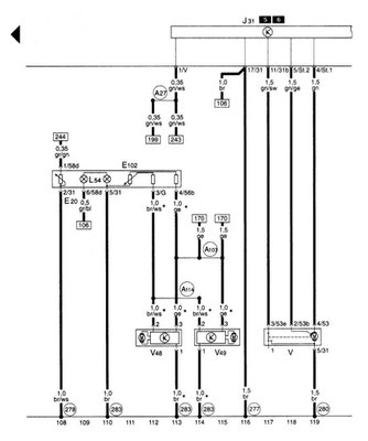
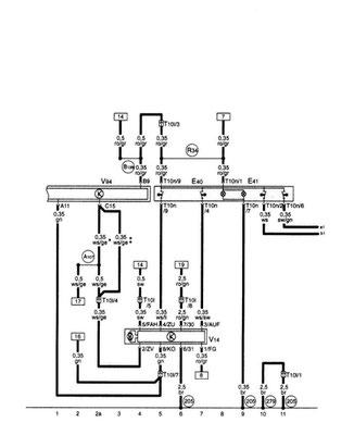
Right-hand stalk switch, windshield wiper and washer, rear window cleaner
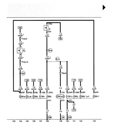
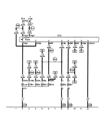
Side lights, brake lights, reversing lights, fog lights
Sound signal, heated rear window, cigarette lighter, ashtray light
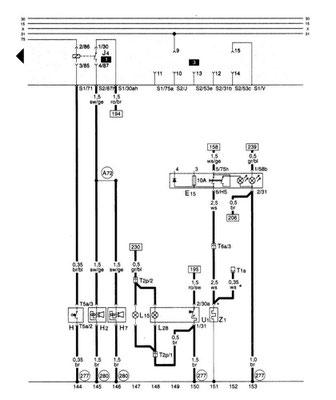
Fuse box, heated washer nozzle, lighting of the glove box, license plate light

Fuse box, heated nozzle, glove compartment lighting, license plate light
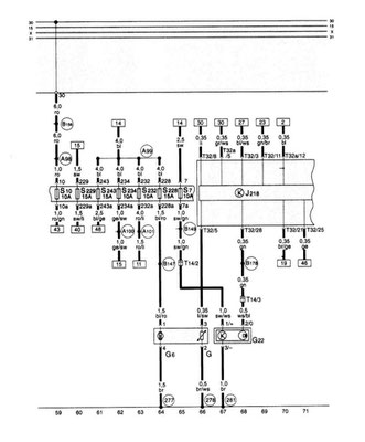
Fuse box
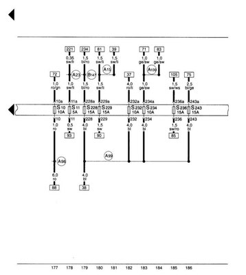
Fuse box, diagnostic plug, radio preparation
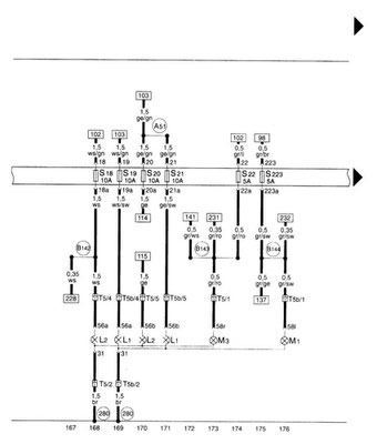
Turn Signals and Alarms

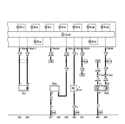
Lamps for trunk lighting, door contact switch
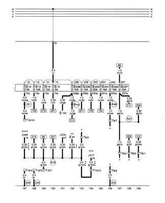
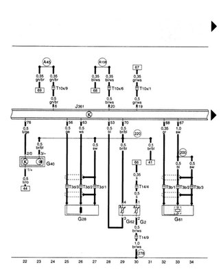
Dashboard unit, combi processor in dashboard assembly, parking brake monitoring
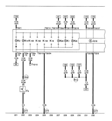
Dashboard unit, combi processor in dashboard block, tachometer, speedometer, fuel reserve indicator, fuel pump, coolant control, oil pressure switch, dial gauge

Dashboard unit, combi-processor in the dashboard unit, reserve / fuel level sensor, warning lamps
Dashboard unit, combi processor in the dashboard unit, anti-theft protection reading coil, speed sensor, warning lamps, seat belt control
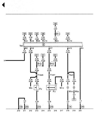
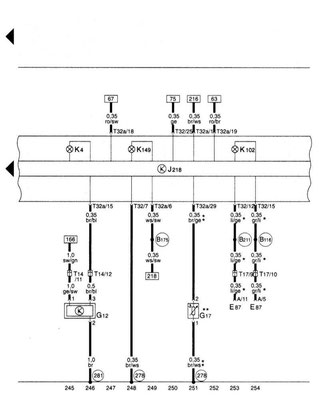
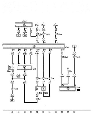
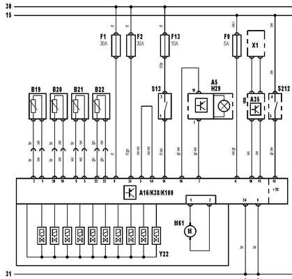
Cooling fan, fresh air fan

Rechargeable battery, starter, generator, main fuse block / rechargeable battery

Control device for Simos, fuel pump relay, injectors, ignition system, Intake manifold switching valve
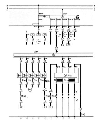
Control device for Simos, detonation sensor, engine speed sensor, coolant temperature sensor, Hall sensor
Control device for Simos, throttle control unit, power steering switch
Control device for Simos, oxygen sensor, air mass meter, solenoid valve of the adsorber system
Dashboard unit, combi processor in dashboard unit, fuel pump, fuel reserve sensor, speed sensor
Trailer


Electric windows, 3-door models (with crushing protection), driver's side
Electric windows, 3-door models (with pinch protection), front passenger side
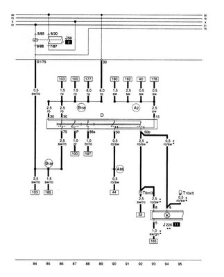
ABS anti-lock braking system and control unit connector
Engine management system 1.6 l
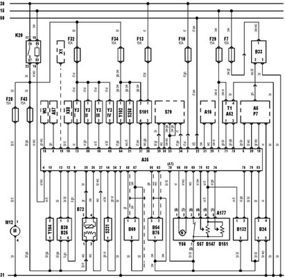
Engine management 1.8 l without turbocharger
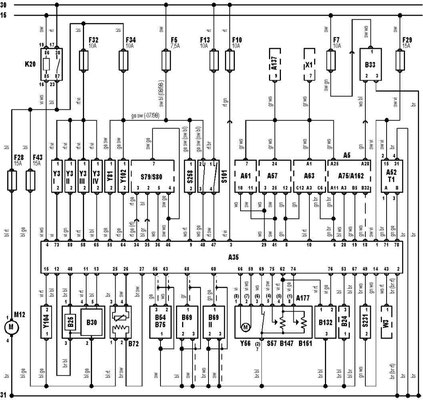
The engine management system 1.8 l with a turbocharger

dwa (Monday, 23 October 2023 11:06)
asdasda fdasd asdsad
Danie (Monday, 06 February 2023 11:16)
Please can you send me the wiring
John (Saturday, 24 September 2022 21:53)
Well done, thank you for diagrams